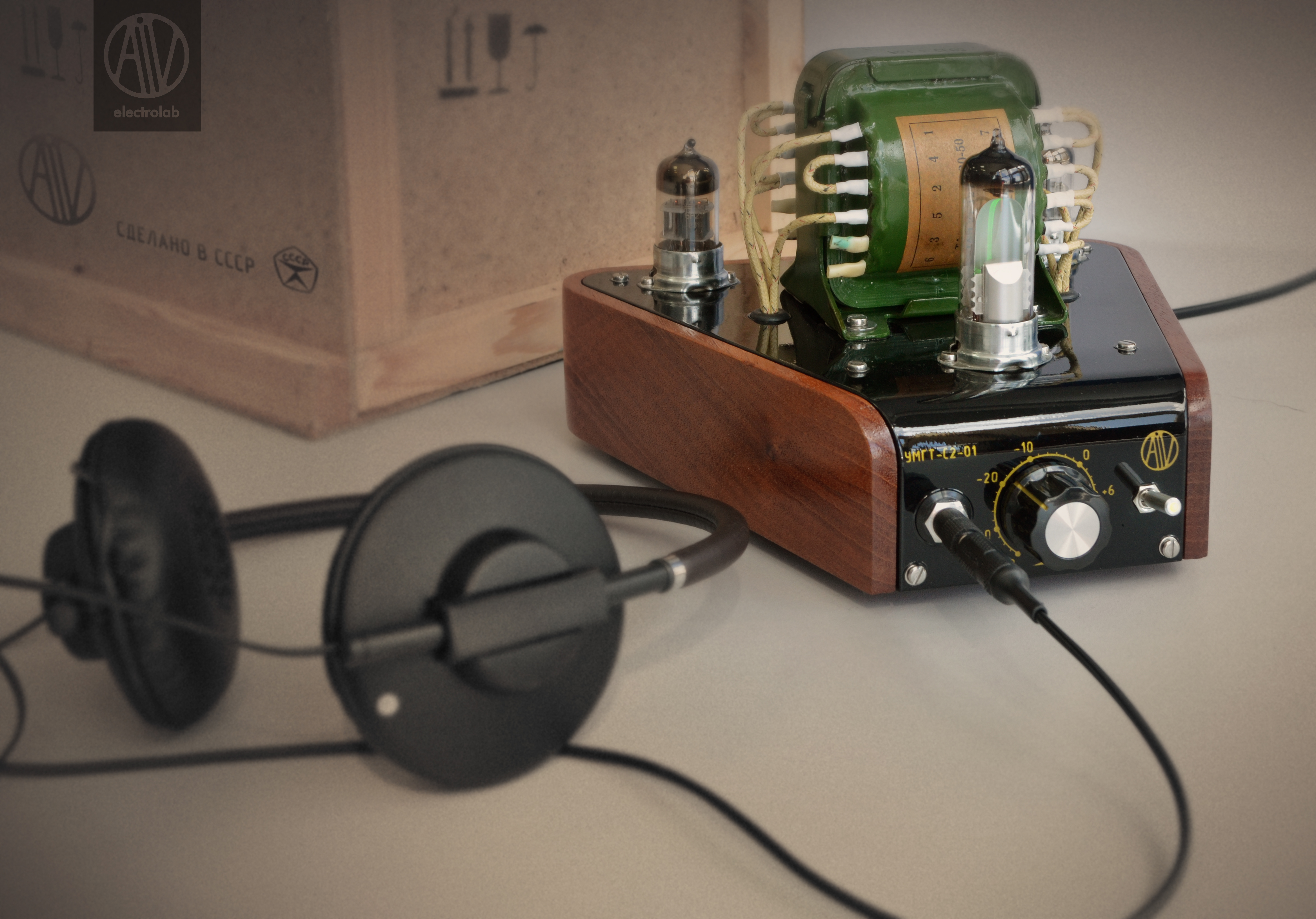
AiV Electronics Company pioneer project was UMGT-S2-01 headphone power amplifier. Named after the Russian acronym, “S2-01” meaning “stereo, model 01).
The idea of attempting to create a tube audio-amplifier arose as far back as in the early 2012.
Due to the fact that the area of tube audio-amplifier design, like any other high-end audio equipment, is a niche area with a large number of its own developments and respected opinions, from the very beginning the creation of something extraordinary in the audio-sound area was not the purpose of the development. The main task was to try out the design technology of tube devices using present-day design techniques, manufacture of metal and wooden products, application of varnishes.
The experience gained during the development and manufacture of this amplifier contributed greatly to the process of AiV Nixie development.
As the working circuit a simple SRPP-cascade circuit based on 6N23P double triodes was applied.
The Circuit Diagram of the Headphone Tube Amplifier based on SRPP-Cascade
We are not going to highlight the operation and peculiarities of this circuit.
The main idea of the development was: the creation of the unique neo-retro design, streamlining of the technologies for the production of wooden bodies, fabrication of steel parts, application of varnishes and labeling.
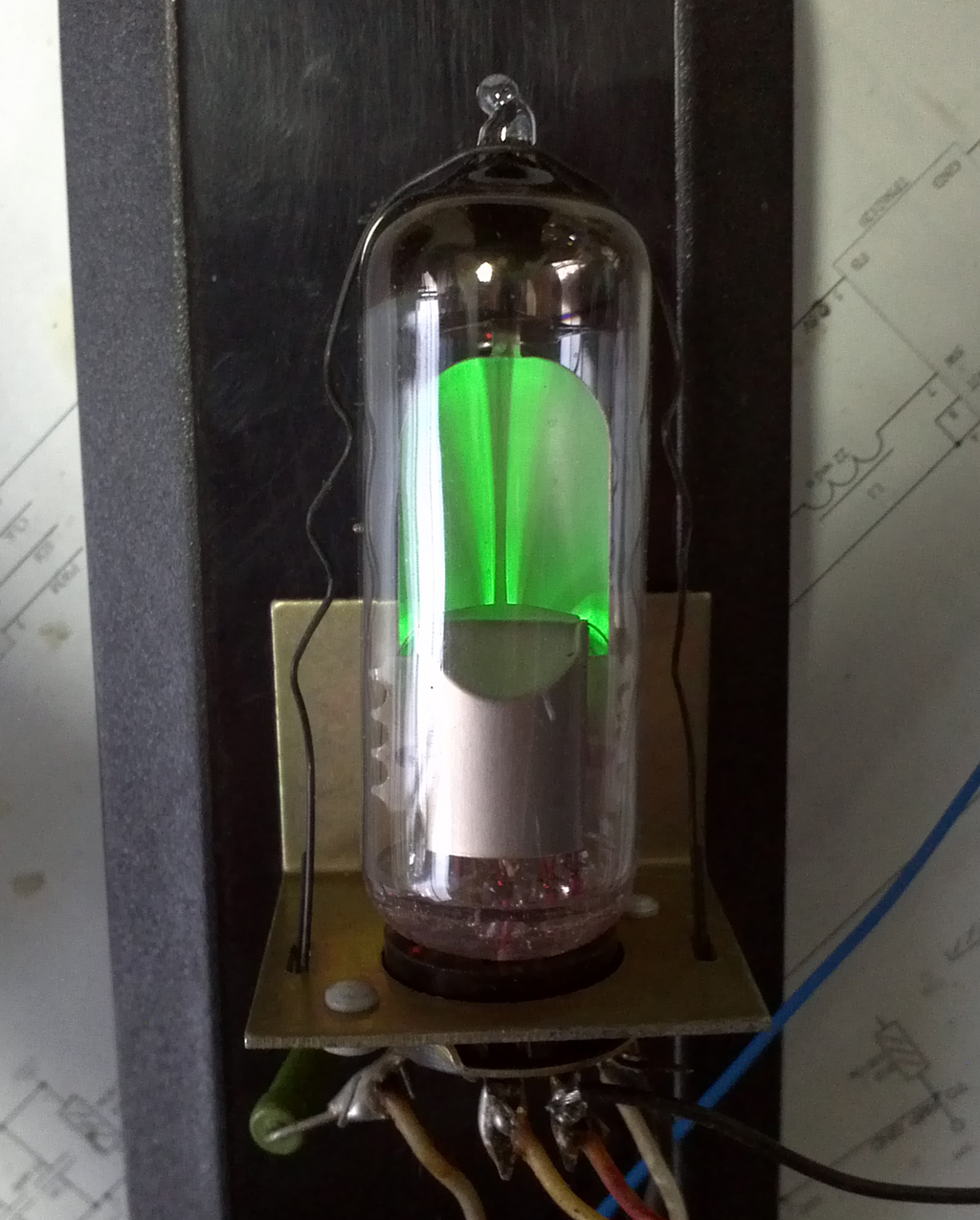
6E1P Indicator Tube
The main functional innovation was the application of 6E1P indicator tube for the signal level display. The task set was not simple: to provide an adequate visualization of the stereosignal on one tube for a different signal volume and different resistance of the headphones used. The task was solved by using and integrated amplifier with the controller programmable gain ratio using digital filtering. The microcontroller simplified a number of other tasks: the implementation of the delay during the high voltage supply and control of the power-on switch illumination.
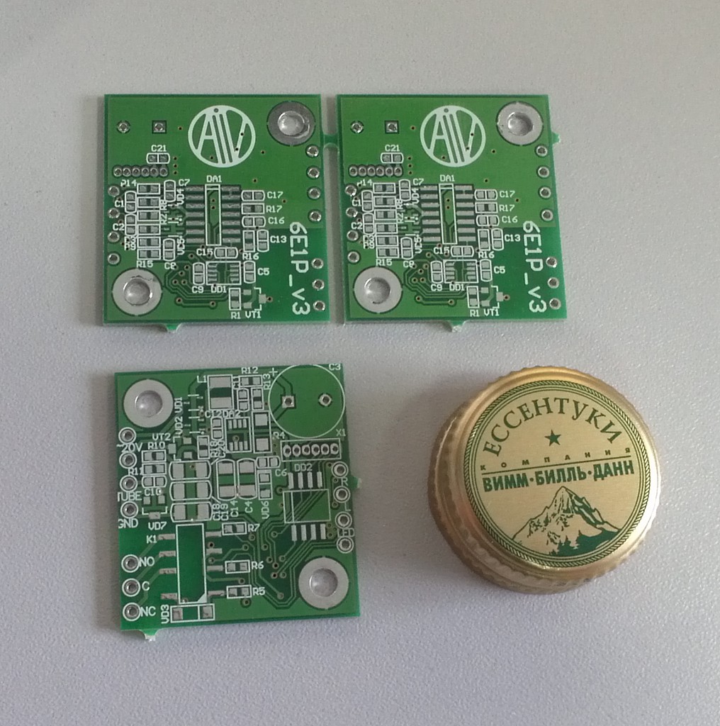
Microcontroller Board
By the late 2012 the amplifier circuit diagram was tested and the most complicated process began: prototype manufacture. Due to the fact that the plan was to assemble not more than one or two devices the task was to manufacture a “batch” specimen (as far as it was possible).
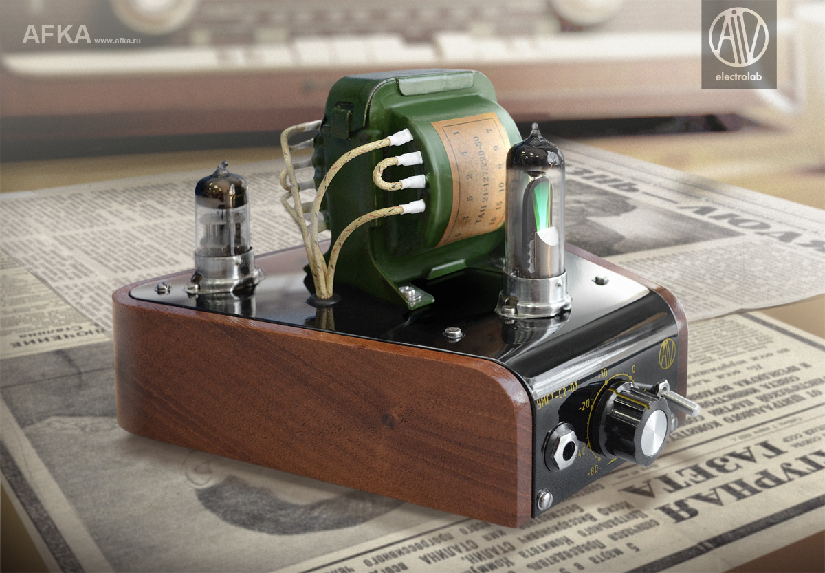
It was decided to use the classic tube device arrangement and make the main part of the body from exclusive tree grades with a cover as an aluminum top plate. The tubes and transformer were supposed to be positioned vertically on the top plate without any protection. We worked out the terms of reference and addressed them to the famous designer Alexander Bazilevsky (www.afka.ru) who had already had some experience in the audio equipment outlook design. Using this brief description Alexander began sketching. The design provided 3 tubes which prompted a triangle-looking design. And soon the world saw a 3D-render of the future device:
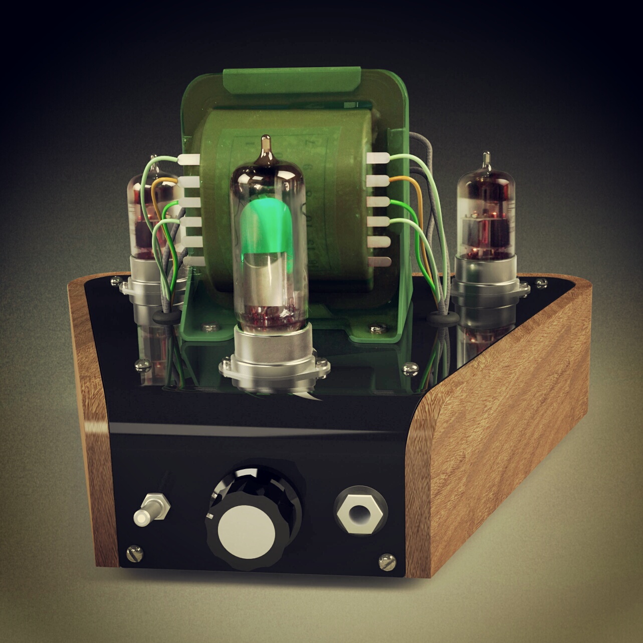
The Way the Designer Did It
It was supposed that the top plate would be made of 2-mm thick aluminum with a large bending radius in the front part. The bend is located in the plate narrowing area. The wooden body should fit the plate with equal gaps along the circle. The body cannot be fabricated in the home conditions with the required accuracy. So we addressed one of the large “Soviet heritage” plants. However, we failed to obtain a worthy result. That is what the device first prototype look like:
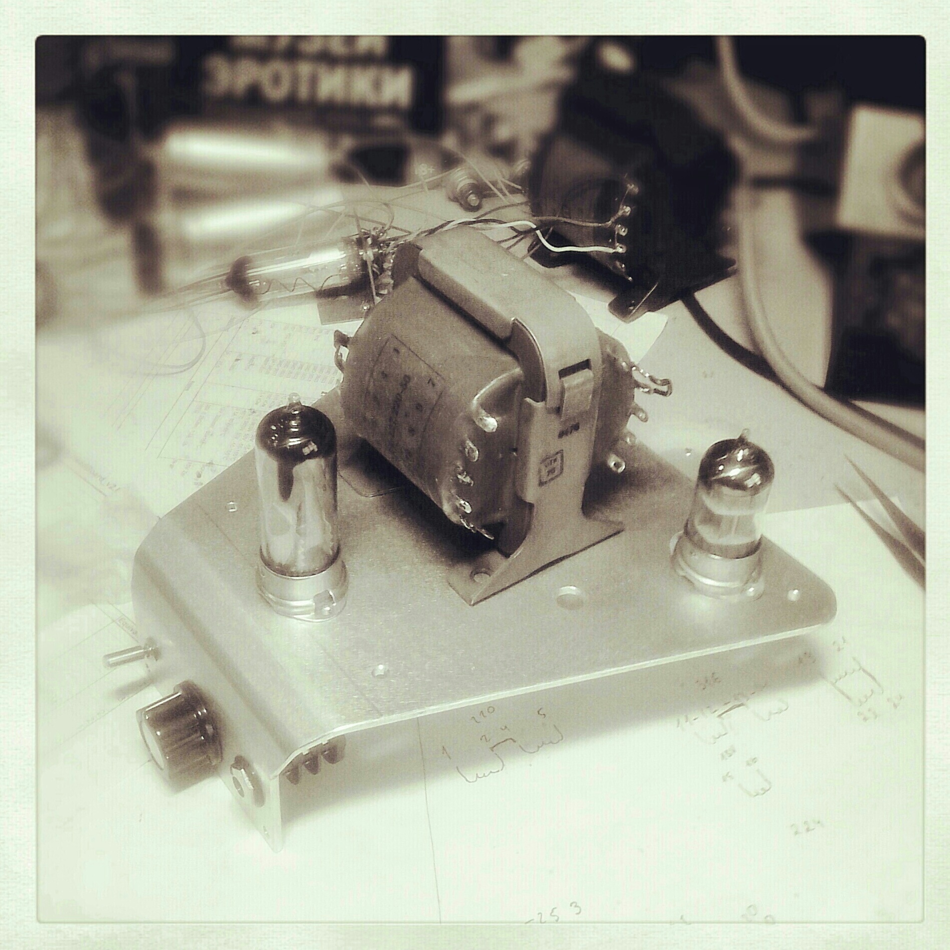
The Way the Plant Made It
Any accuracy was out of the question because after a curved marking with a nail (despite the notes in the drawing) the part was finalized in a very talented manner with a file (in the curved location) and became even more curved. The holes were not aligned, the bend was made in three steps by guesswork. Generally speaking, only at the quickest look it was possible to say that the part looked like the one in the drawing. We rejected the services of this plant, so we did with the services of “jacks of all trades” ready to make everything for a bottle of vodka. Moreover, the fabrication of this “item” took nearly 3 months! We had to look for more concerned people.
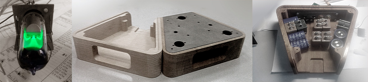
Some time after we found a plant with the stamp for bending with the required radius and laser metal-cutting machines. We replaced 2-mm aluminum for 3-mm steel. The photos below provide the comparison of the parts made at the two plants.


And although in the bending locations the edge noticeably protrudes, this defect may be easily removed using a file and this was done.
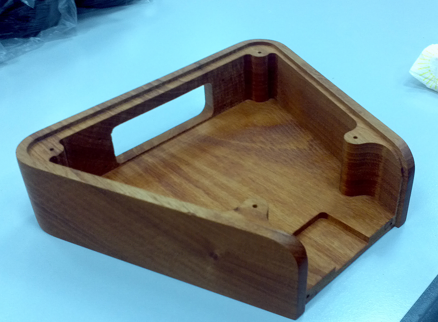
It was late spring 2013 and the next step was to make the wooden part of the body. The wooden model was updates by the metal plate available. After the consultations with the wood-processing experts and sellers of the exclusive wood species mahogany was selected for the body manufacture (country of origin – Honduras). This tree species is classified as a red wood and has a high density, low temperature expansion and high stability. The mahogany is often used to make guitars and other musical instruments.
The initial task was to make a solid-wood body! No compromise! Nowadays most of the wooden products are made glued. We are speaking of the solid wood products, to chipboard, not plywood ones. A typical technology is cutting the solid wood into planks and their layered gluing at different angles. From the briquette produced the required part is milled as if it were solid wood. The gluing is performed to compensate for the subsequent wood deformations which will occur later due to moisture and temperature. These deformations are inevitable in case of large temperature variations and may result in the wood cracking or substantial deformations of the product. Gluing is often performed for two reasons: to cheapen the manufacture process when the part is made from the wood remnants and solid wood of the required size is not available. But still, we decided to take a risk and make a solid-wood body hoping to later work out a reliable coating protecting the wood against ambient conditions.
One small wood-processing plant in Moscow region undertook making the body. The body was made on a five-coordinate numerically-controlled machine. The result was brilliant.

Now, when we had metal parts and wooden parts fitting them, we came up to the experiments with the coating for steel and wood. It took the entire summer 2013. It was more or less clear, what to do with the steel: priming, painting, varnishing. With the wood the problem was more complicated. The device outline dimensions and gaps did not allow us to use a thick varnish protection ad the design provided silk-matte wood coating, not glossy. The solution was using special oils for the wood. We tried a lot of different oils. As a result the body was impregnated with a special furniture oil grade and then covered with the medium-glossy oil on top. Therefore, the wood coating was developed which enabled the reduction of the environmental impact on the wood and retaining the wood visual structure. This body has been stored at home since 2013 and it did not crack or dry up. The tests are underway…
A separate nuisance was fasteners’ purchase. The amplifier neo-retro style provided using only cleaved-head screws and bolts! But such screws are not used or manufactured for 20 years now. We could use screws and bolts from the old-time devices but all the bolts had twisted slots (it is impossible to wind the screw in and out without twisting the slot! You remember the way it was, don’t you?), and besides, these second-hand bolts quite often were corroded. It was extremely desirable to use specifically stainless-steel fasteners. It took us enormous efforts to find probably the only company in Russia which dealt in suitable stainless steel cleaved-head bolts. It was the company with an teaser name – Papa Bolt.
The coating did not augur any difficulties. A bit unconventional was the steel phosphate priming. For this purpose a special rust converter performing the surface chemical zinc-plating and phosphating was used. On top the steel cover was coated with several layers of black paint. But suddenly after the paint application a question arose: how to make labeling, logo and designations onto the front and rear sides? Obviously, it should be done before the varnish application. On the designer’s 3D-render available the amplifier did not bear any insignia. The project which was started as a try-out had already become too serious. An artist, designer, electronics engineer, topologist, programmer worked at the project. Some parts were made by four different plants. Components and materials were purchased from two dozens of outfits. The device needed a name! A logo was required! A brand was necessary!
The company name had to meet several criteria: a short name, preferably – an acronym, similar to the names of other renowned companies manufacturing audio equipment but without any hint to the audio (a universal name). This name was born very fast: AIV. This name is the acronym of the surname, given name and patronymic of the main creator of the project, the person responsible for everything which was going on. For a long time we argued what was to follow this name: Electronics, Electrolab, Company, Industries, Corporation. Finally we stopped on AIV Electronics as the most neutral-sounding version.
The company logo was supposed to include its name and remind the logos of tube electronics manufacturers. Here are the logos of some companies which manufactured radio tubes from the 1930s to the 1980s.
![]()
Having reviewed a lot of logotypes of the tube electronics manufacturers since the mid-XX century the AiV Electronics logo was created:
![]()
To be continued…